
Spread of fire: Junction of party / compartment walls and roofs
[Scroll to the end of the page to download this article as a handy PDF guide]
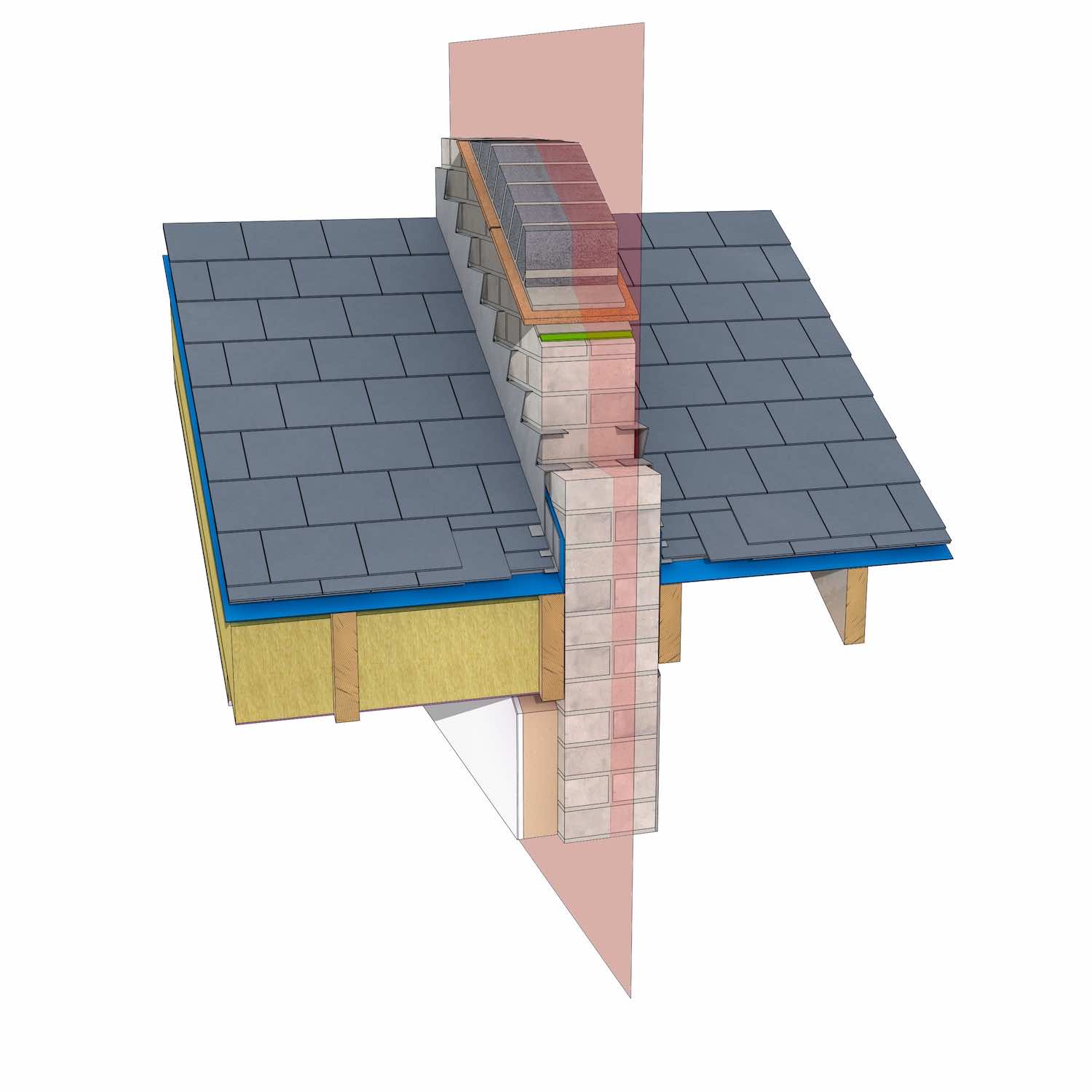

This guide breaks down the key requirements from Building Regulations Approved Document Part B1 for fire-stopping at roof junctions, explains the difference between cavity barriers and fire-stopping, and provides practical construction details to help you design robust solutions.
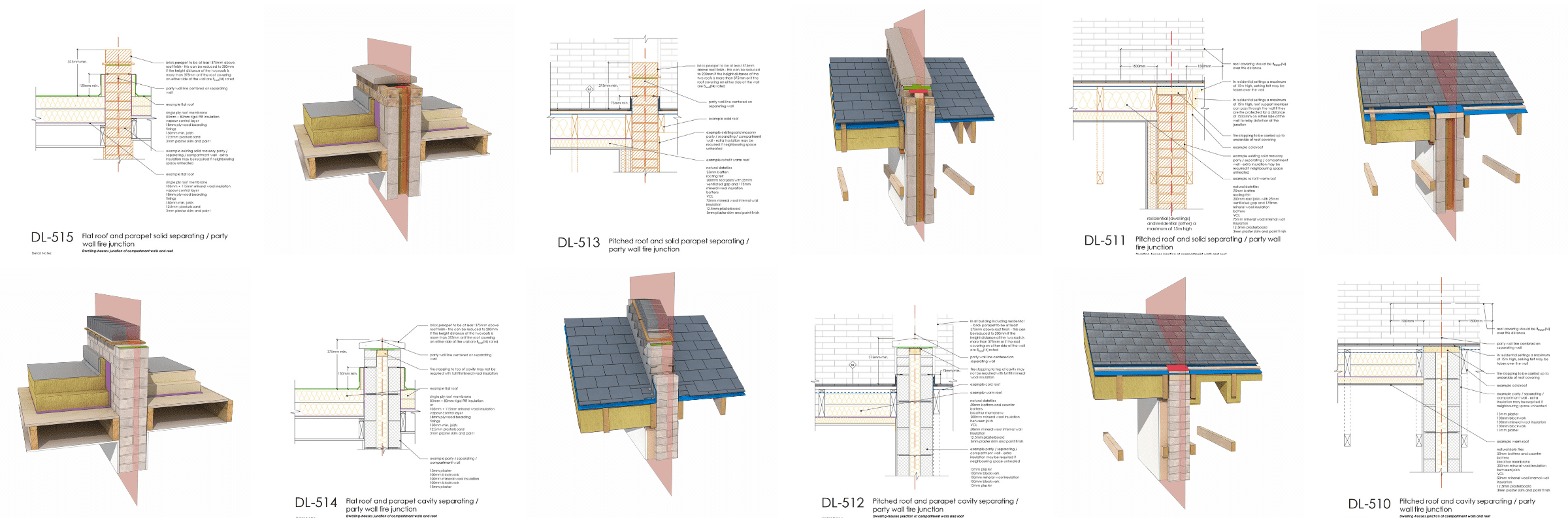
We have created a series of details that help you navigate the different types of party / compartment walls, roof junctions and more. Check out the full set and join our membership to download.
What is classified as ‘building works’?
Any ‘building works’ as classified under The Building Regulations 2010 will be required to meet the current Building Regulations relevant to those works.
Some of these works include:
(a) the erection or extension of a building;
(b) the provision or extension of a controlled service or fitting in or in connection with a building;
(c) the material alteration of a building, or a controlled service or fitting, as mentioned in paragraph (2);
(d) work required by regulation 6 (requirements relating to material change of use);
(e) the insertion of insulating material into the cavity wall of a building;
(f) work involving the underpinning of a building;
(g) work required by regulation 22 (requirements relating to a change of energy status);
(h) work required by regulation 23 (requirements relating to thermal elements);
(i) work required by regulation 28 (consequential improvements to energy performance).
Difference between Cavity barriers and Fire-stopping
Within the Approved Document BR Part B a cavity barrier is defined as:
A construction within a cavity, other than a smoke curtain, to perform either of the following functions:
- Close a cavity to stop smoke or flame entering.
- Restrict the movement of smoke or flame within a cavity.
Cavity barriers should not be confused with fire-stopping details.
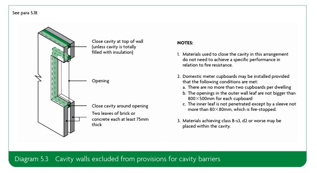
Diagram 5.3 – Cavity walls excluded from provisions for cavity barriers taken from Approved Document B Volume 1 Dwellings showing location of cavity closer.
A seal provided to close an imperfection of fit or design tolerance between elements or components, to restrict the spread of fire and smoke and should be designed and specified to the same resistances as the compartment.
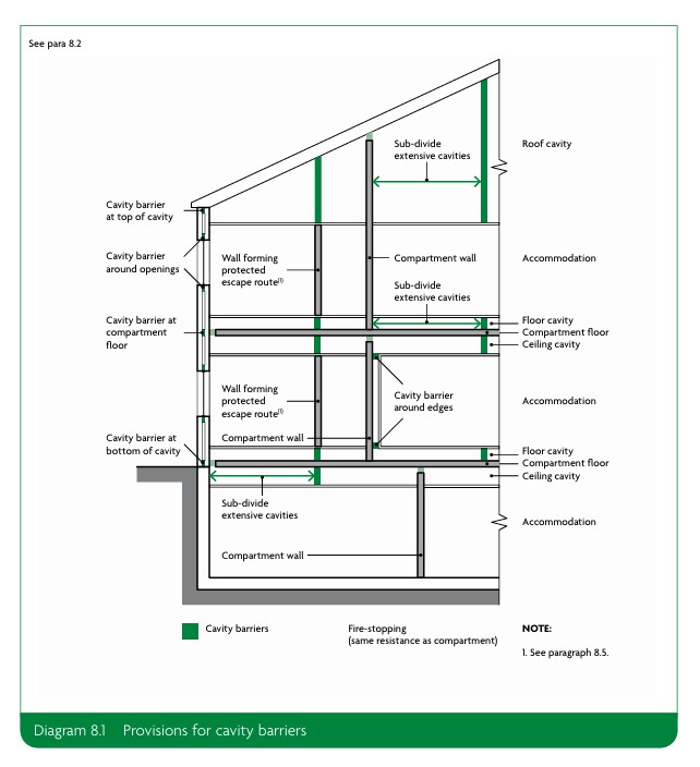
Diagram 8.1 – Provisions for cavity barriers taken from Approved Document B Volume 1 Dwellings showing cavity barrier locations and fire-stopping in light green with the same resistance and the compartment wall / floor / roof.
Examples of cavity barriers include cavity closers around windows and cavity barriers to the top of walls before the roof structure.
An example of a fire-stopping detail is the junction between a party / compartment wall and the roof.
Breaking down the Building Regulations – Junction of compartment wall with roof
Paragraphs 5.11 – 5.15 of Building Regulations Part B1 set out the requirements for the fire-stopping detail between a party / compartment wall and the roof.
5.11 A compartment wall should achieve both of the following.
-
- Meet the underside of the roof covering or deck, with fire-stopping to maintain the continuity of fire resistance.
- Be continued across any eaves.
5.12 To reduce the risk of fire spreading over the roof from one compartment to another, a 1500mm wide zone of the roof, either side of the wall, should have a covering classified as BROOF (t4), on a substrate or deck of a material rated class A2-s3, d2 or better, as set out in Diagram 5.2a.
Thermoplastic rooflights that, because of paragraph 12.7, are regarded as having a BROOF(t4) classification are not suitable for use in that zone.
5.13 Materials achieving class B-s3, d2 or worse used as a substrate to the roof covering and any timber tiling battens, fully bedded in mortar or other suitable material for the width of the wall (Diagram 5.2b), may extend over the compartment wall in buildings that are a maximum of 15m high.
5.14 Double-skinned insulated roof sheeting should incorporate a band of material rated class A2-s3, d2 or better, a minimum of 300mm in width, centred over the wall.
5.15 As an alternative to the provisions of paragraphs 5.12 to 5.14, the compartment wall may extend through the roof for a minimum of either of the following (see Diagram 5.2c).
-
- Where the height difference between the two roofs is less than 375mm, 375mm above the top surface of the adjoining roof covering.
- 200mm above the top surface of the adjoining roof covering where either of the following applies.
- The height difference between the two roofs is 375mm or more.
- The roof coverings either side of the wall are of a material classified as BROOF(t4).
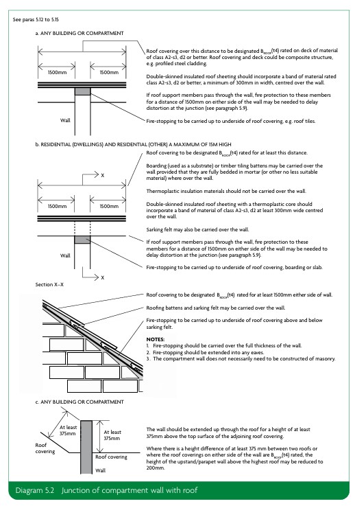
Diagram 5.2 from Building Regulation Approved Document Part B Volume 1 – Showing junction of compartment wall with roof diagrammes
What is BROOF(t4)
When designing anything at roof level for dwellings or single family homes, you can ensure compliance with the building regulations if all materials on the roof are rated BROOF(t4).
BROOF(t4) refers to the highest fire rating classification for roof coverings according to the European classification system BS EN 13501-5 since the national classification system BS 476-3:2004 no longer applied after 2019 and the new Approved Document Part B.
Materials such as natural slate and clay tiles are usually BROOF(t4) rated but you should consult the supplier and manufacturer to obtain the fire certification.
Specifying this type of roof is not always possible as there can be certain trims and finishes which may not be certified. There are therefore a number of ways, depending on the roof types, which can be designed to mitigate the risk of fire spreading through the roof.
Detail examples of junction of party / compartment wall with roof
We have included a series of construction details which help to illustrate the requirements of first stopping at the junction of a party wall / compartment wall with the roof.
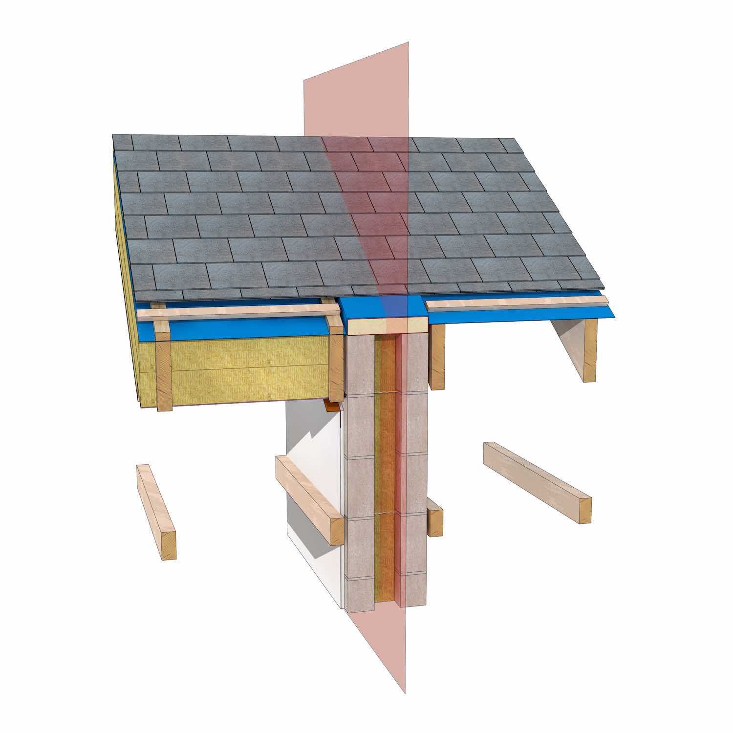
DL510 – Pitched roof and cavity separating / party wall fire junction
This detail shows a cavity party / compartment wall and possible requirements for fire. Some of the key features include:
- The roof covering should be BROOF(t4) for at least 1500mm to either side of the wall.
- Fire-stopping to be carried up to the underside of the roof covering.
- In residential settings a maximum of 15m high, non-fire rated elements such as sarking felt may be taken over the wall.
This detail shows both a warm (insulation between and under the rafters) and cold (insulation at ceiling level) pitched roof.
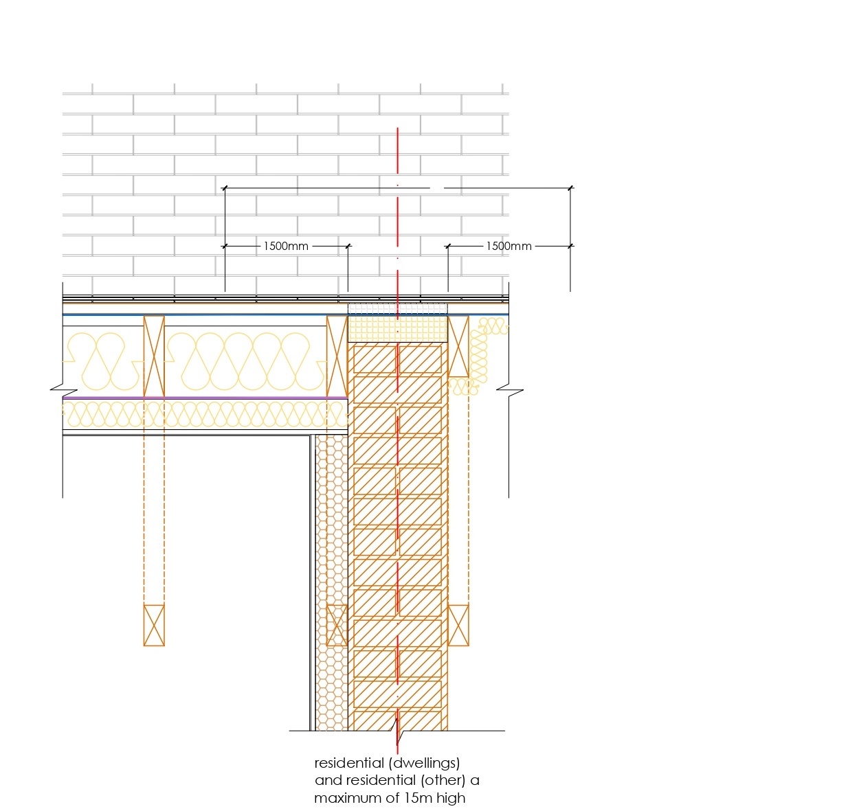
DL511 – Pitched roof and solid separating / party wall fire junction
This drawing illustrates a possible existing solid masonry party / compartment wall and key requirements under BR Part B1 including:
- The roof covering should be BROOF(t4) for at least 1500mm to either side of the wall.
- Fire-stopping to be carried up to the underside of the roof covering.
- In residential settings a maximum of 15m high, non-fire rated elements such as sarking felt may be taken over the wall.
- In residential settings a maximum of 15m high, roof support members such as roofing battens can pass through the wall if they are fire protected for a distance of 1500mm on either side of the wall to relay distortion at the junction.
This detail shows both a warm (insulation between and under the rafters) and cold (insulation at ceiling level) pitched roof.
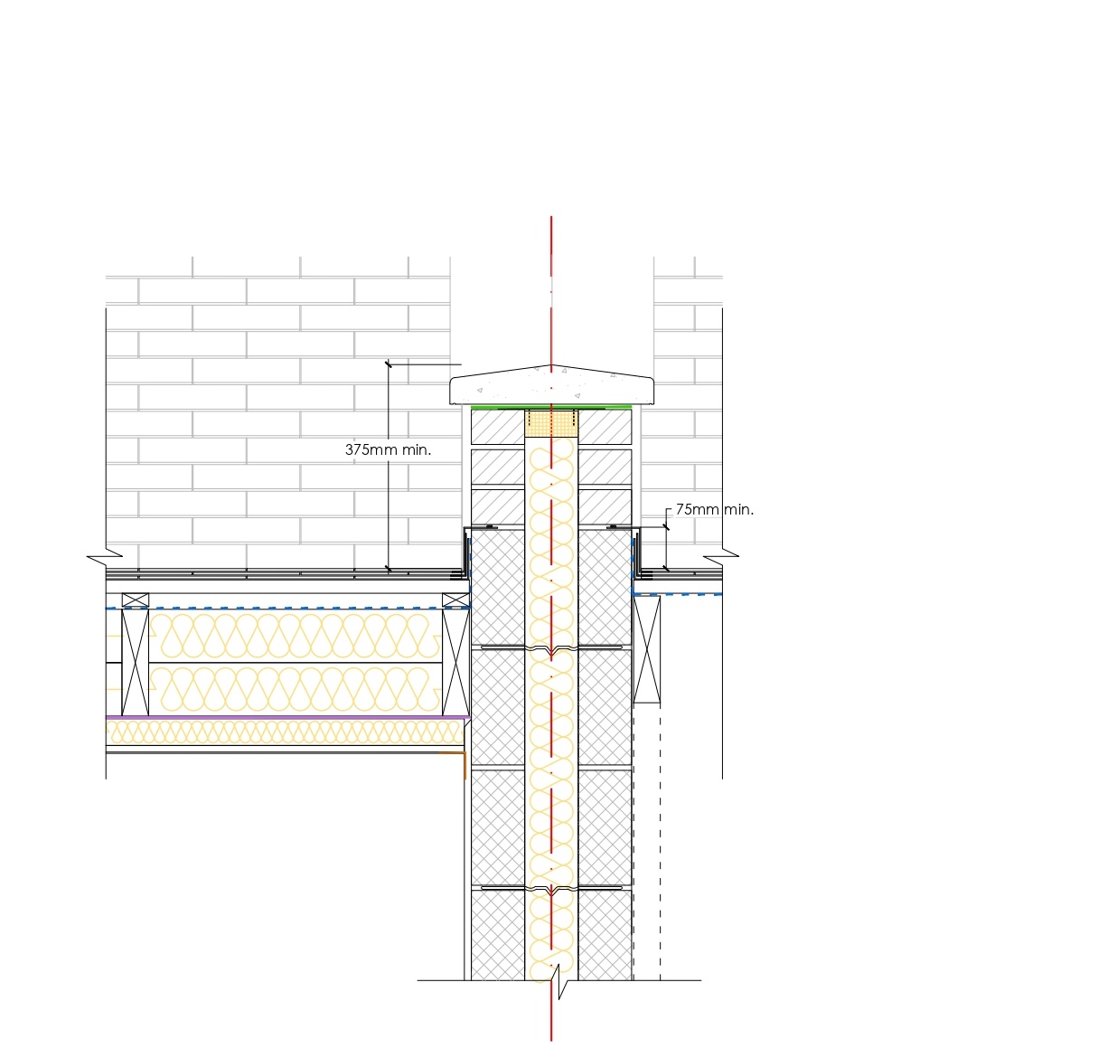
DL512 – Pitched roof and parapet cavity separating / party wall fire junction
If a BROOF(t4) roof covering is not possible as described above, this detail shows how a parapet can be used as a fire stopping method within a cavity wall and pitched roof construction and includes:
- In all buildings including residential – a brick parapet to be at least 375mm above roof finish – this can be reduced to 200mm if the height distance of the two roofs is more than 375mm or if the roof covering on either side of the wall are BROOF(t4) rated.
- Fire-stopping to top of cavity may not be required with full fill mineral wool insulation
This detail shows both a warm (insulation between and under the rafters) and cold (insulation at ceiling level) pitched roof.
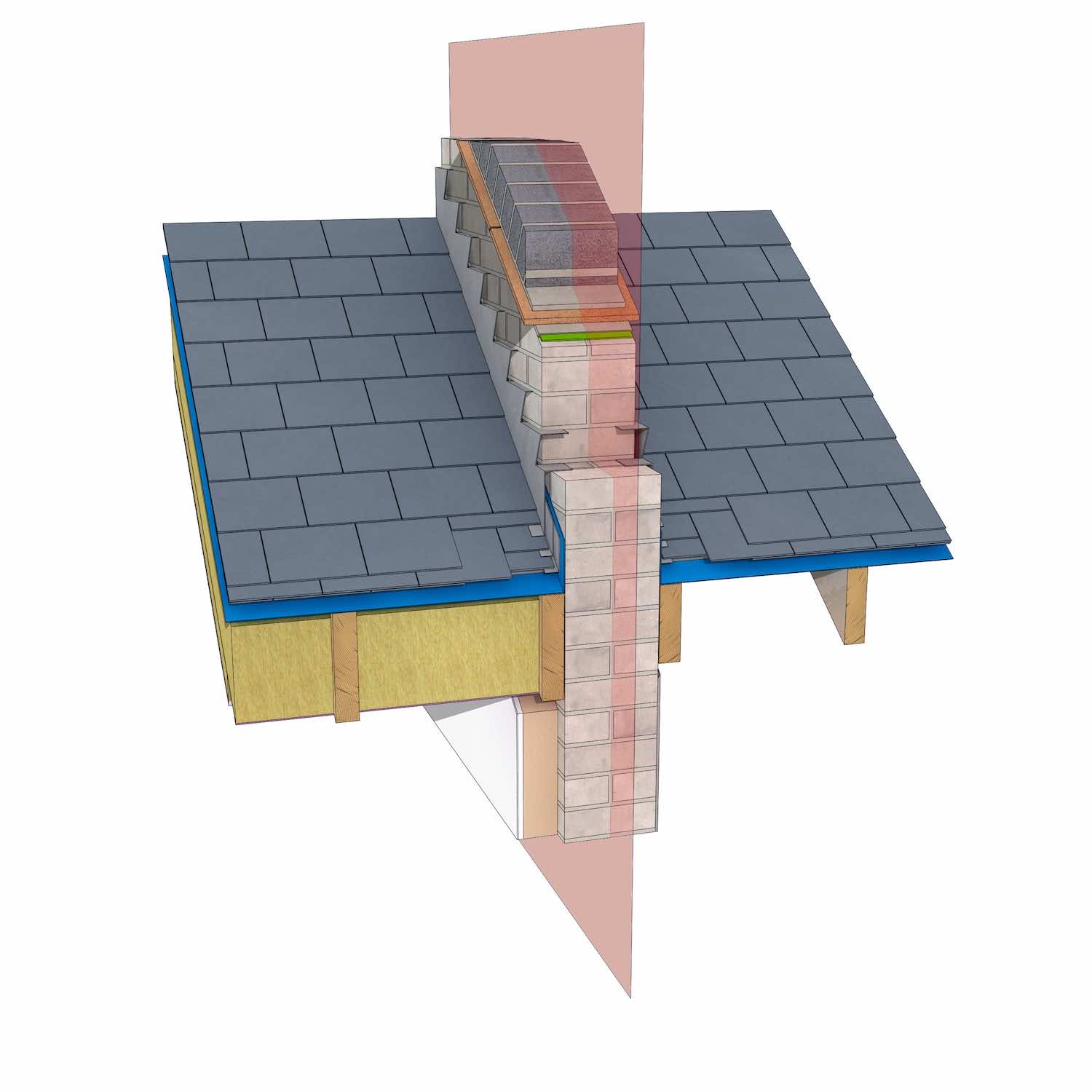
DL513 Pitched roof and solid parapet separating / party wall fire junction
This detail illustrates a solid masonry wall separating / party wall junction with a pitched roof where a BROOF(t4) roof covering is not possible and a parapet is used as a fire stopping method. It includes:
- In all buildings including residential – a brick parapet to be at least 375mm above roof finish – this can be reduced to 200mm if the height distance of the two roofs is more than 375mm or if the roof covering on either side of the wall are BROOF(t4) rated.
This detail shows both a warm (insulation between and under the rafters) and cold (insulation at ceiling level) pitched roof.
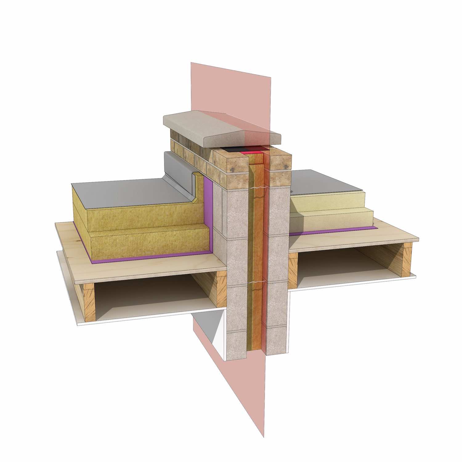
DL514 – Flat roof and parapet cavity separating / party wall fire junction
If a BROOF(t4) roof covering is not possible as described above, this detail shows how a parapet can be used as a fire stopping method within a cavity wall and flat roof construction and includes:
- In all buildings including residential – a brick parapet to be at least 375mm above roof finish – this can be reduced to 200mm if the height distance of the two roofs is more than 375mm or if the roof covering on either side of the wall are BROOF(t4) rated.
- Fire-stopping to top of cavity may not be required with full fill mineral wool insulation
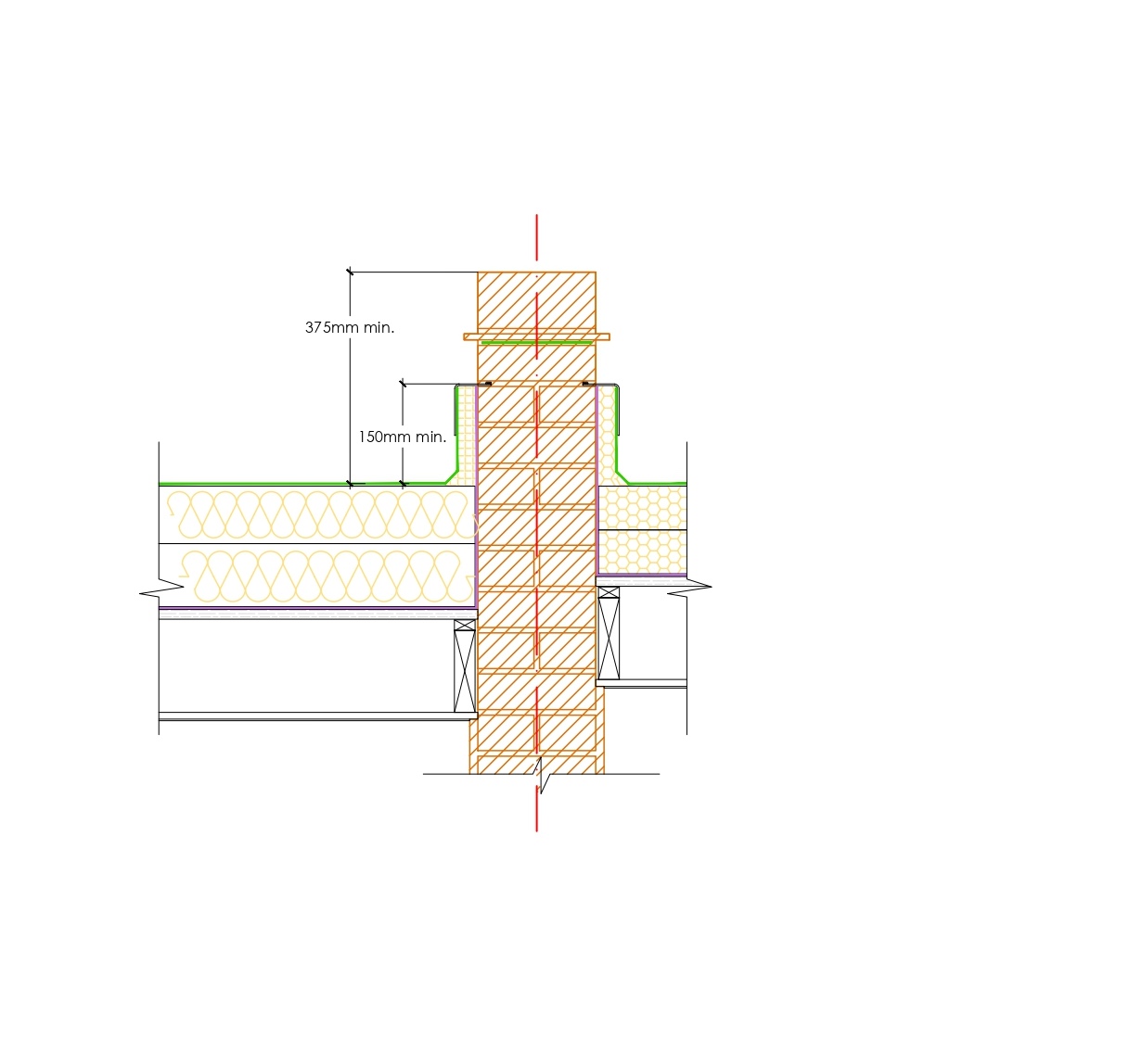
DL515 – Flat roof and parapet solid separating / party wall fire junction
This detail illustrates a solid masonry wall separating / party wall junction with a flat roof where a BROOF(t4) roof covering is not possible and a parapet is used as a fire stopping method. It includes:
- In all buildings including residential – a brick parapet to be at least 375mm above roof finish – this can be reduced to 200mm if the height distance of the two roofs is more than 375mm or if the roof covering on either side of the wall are BROOF(t4) rated.
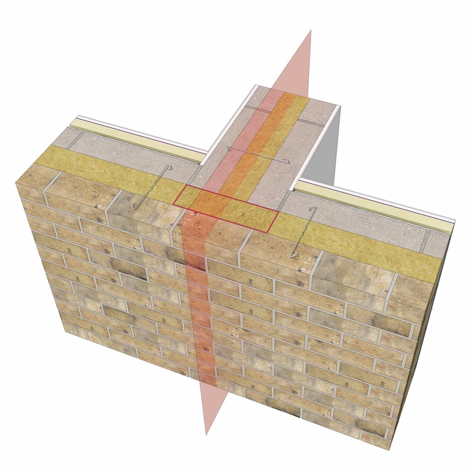
DL516 – New separating / party cavity masonry wall to exterior wall junction – Plan
This detail does not show a roof junction but how the fire-stopping at the top of a cavity should be maintained throughout the party / compartment wall junction.
Conclusion
Fire-stopping at party wall and roof junctions may seem complex, but it follows clear principles. If you can specify BROOF(t4) rated materials for 1500mm either side of the compartment wall, compliance becomes straightforward. When that’s not possible, parapets offer an effective alternative solution.
Download the Guide
Want to keep this for later? Enter your email below to get instant access to this free download — plus other helpful resources, guides, and updates from the Detail Library to support your projects and professional development.

Download the Details
The key is to plan these details early in your design process, especially for loft conversions or roof extensions. Our construction details DL510-DL516 provide practical starting points for common scenarios, but always consult the full Approved Document Part B1 for your specific project to ensure you achieve both regulatory compliance and robust fire protection between properties.
Disclaimer
Article written March 2026 and reflects the active guidance and regulations at time of writing.
This article is an introduction to the principles and requirements of the Approved Document Part B for England for spread of fire and compartment junctions at roof level – but in no way a substitute to the full guidance document.
References
Building Regulations
- Approved Document B Volume 1 (Dwellings), 2019 edition incorporating 2020, 2022, 2025, 2026 and 2029 amendments
- Approved Document B Volume 2 (Buildings other than Dwellings), 2019 edition incorporating 2020, 2022, 2025, 2026 and 2029 amendments
https://www.gov.uk/government/publications/fire-safety-approved-document-b
British Gypsum specification selection
Metal frame internal partitions
Timber frame internal partitions
https://www.british-gypsum.com/specification/white-book-specification-selector/timber-frame
Internal floors
https://www.british-gypsum.com/specification/white-book-specification-selector/floors
Ceilings
https://www.british-gypsum.com/specification/white-book-specification-selector/ceilings
Related Reading

Author
Written by Aida Rodriguez-Vega, BA(Hons) MArch DipArch ARB, architect and researcher. At the Detail Library, Aida keeps busy by carrying out technical research and drawing new details for the ever-growing library.
